World Coordinate System
Motivation
Attempting to decouple the SCCharts Controller and physics calculations (amongst other things) from fixed pixel coordinates a world coordinate system was introduced. This coordinate system has its origin in the center between the two bottom flipper tips. Standing in front of the flipper the Y-axis points upwards on the playing field and the X-axis points to the right. One unit in the world coordinate system corresponds to 1m.
The main program relies on a (at compile-time present) transformation matrix definition which can be generated and tested with a small standalone tool. Testing requires recompilation of the tool. As there is no depth information available, points in the image that are in the same 2D position of an orthographic parallel view onto the playing field will be in different positions with the generated transformation, so this solution is certainly not exact.
Calibration
Compiling
make calibrate
This produces a binary file calibrate in the same directory.
Usage
Button | Function |
|---|---|
1-4 | Choose the index of the point to set |
t | Enters a test mode, which prints clicked pixel coordinates in the world coordinate system via the configured transformation matrix in the console. This matrix must be present in the file calibration_config.h at compile time. |
w | Generates and writes a transformation matrix from the four points (if all are present) into the file calibration_config.h
|
q | Quits the program |
Reference Points
Point # | Point in Image | Description (when looking at flipper) | Position in World Coordinates (Measured in meters) |
|---|---|---|---|
1 | top right | Top of the left outlane detector wire | -0.203, 0.106 |
2 | bottom right | Horizontal middle of the top edge of the black square on the tube shaped graphic | -0.164, 0.685 |
3 | bottom left | Bottom right corner of the letter 'E' trigger (right side of the ramp) | 0.199, 0.637 |
4 | top left | Bottom of the right outlane detector wire | 0.200, 0.103 |
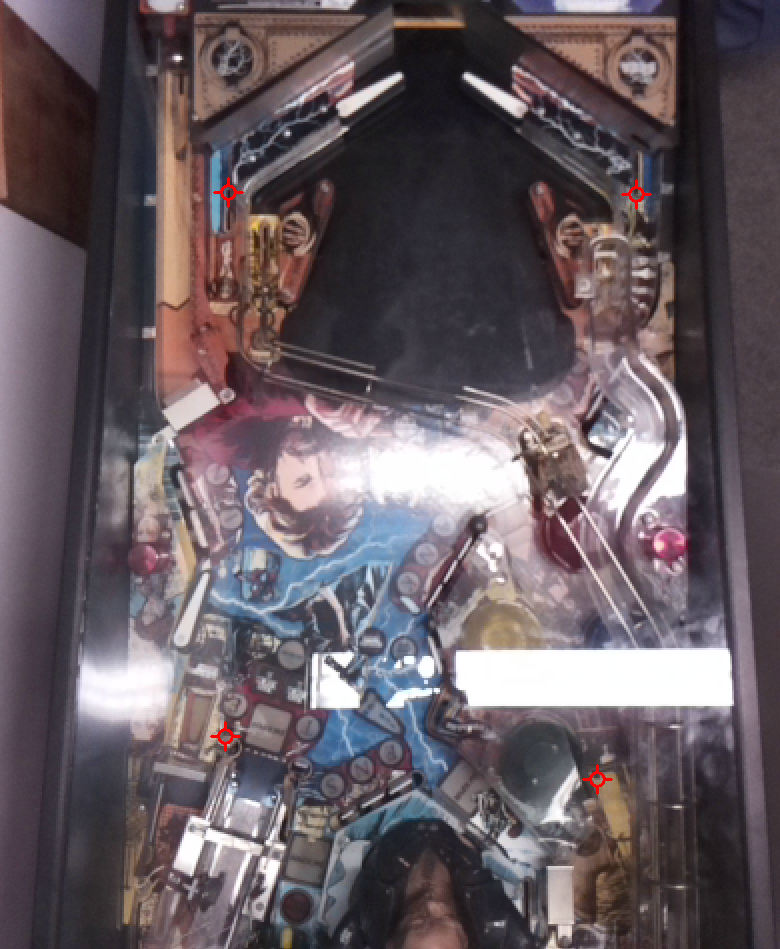
Uncropped Image
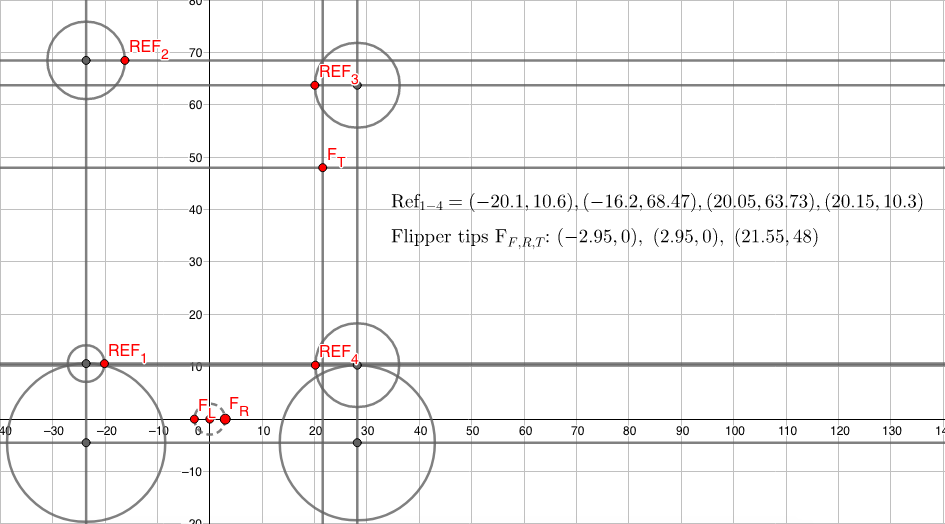
Geogebra File
The reference points used in the calibration (see table) were empirically corrected to the left, as the coordinate system resulting from the generated transformation was slightly shifted to the right. This may have been the case because it is hard to exactly match the reference points to pixels in the image. Subsequent calibrations may yield different errors in the coordinate system.