JSON Graph Format
The JSON Graph Format
JSON (JavaScript Object Notation) is an open standard format that is widely used and accepted as interchange format on the web. JSON consists of arbitrary key-value pairs. We specify some conventions to represent a graph within this format.
We specify positions of nodes and edges relative to parent nodes, see our KLayoutData Meta Model documentation for further information.
The JSON graph format comprises of four basic elements - Nodes, Ports, Labels, and Edges.
- Each element has an 'id' that identifies it uniquely.
- The first three elements can hold a position and dimension.
- Edges on the contrary can hold bend points specifying where the edge changes direction.
- Nodes can contain child nodes and hold ports that specify attachment points of edges.
- Nodes holding child nodes can specify a padding.
- Multiple edges can be attached to the same port, the port is attached to the node itself.
- All elements can hold labels (despite the label itself).
- All elements can hold properties which represent additional information to the layout algorithm.
Examples
Below are some example graphs in the JSON graph format. You can hop to the Live section of our web service and try them! If you use SVG as output format the graph will be rendered as an SVG image directly within your browser.
Minimal
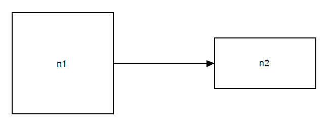
The following example shows a very simple graph consisting of two nodes connected by one edge. Each node owns a width and height as well as a label.
id: "root", // root node
children: [{
id: "n1", // node n1
labels: [ { text: "n1" } ],
width: 100,
height: 100,
},{
id: "n2", // node n2
labels: [ { text: "n2" } ],
width: 100,
height: 50
}],
edges: [{
id: "e1", // edge n1 -> n2
source: "n1",
target: "n2"
}]
}

Hierarchy and Ports
This example illustrates nesting of nodes to establish hierarchy. The node n2 serves as parent node for nodes n3 and n4. The latter two nodes are connected via edge e2. Furthermore, edge e1 is connected to port n2_p1 of node n2.
id: "root",
children: [{
id: "n1",
labels: [ { text: "n1" } ],
width: 100,
height: 100
},{
id: "n2",
labels: [ { text: "n2" } ],
width: 100,
height: 50,
ports: [{
id: "n2_p1",
width: 10,
height: 10
}],
children: [{
id: "n3",
labels: [ { text: "n3" } ],
width: 40,
height: 40
},{
id: "n4",
labels: [ { text: "n4" } ],
width: 40,
height: 40}
],
edges: [{
id: "e4",
source: "n3",
target: "n4"
}]
}],
edges: [{
id: "e1",
labels: [ { text: "e1" } ],
source: "n1",
target: "n2",
targetPort: "n2_p1"
}]
}

Element Properties
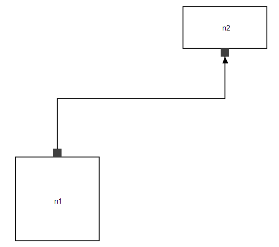
All graph elements can hold further properties that specify certain behavior. In the example below, the both nodes have FIXED_SIDE portConstraints, indicating that the ports may also be moved on their respective side. The side of each port is specified using the portSide property.
Note that properties might be coupled with a certain layout algorithm and hence are not always available. The two properties used in this example are only available for our Klay Layered algorithm.
id: "root", // root node
children: [{
id: "n1", // node n1
labels: [ { text: "n1" } ],
// node n1 has fixed port constraints
properties: {"de.cau.cs.kieler.portConstraints": "FIXED_SIDE"},
width: 100,
height: 100,
ports: [{
id: "p1",
width: 10,
height: 10,
// port p1 should be located on the north side
properties: {"de.cau.cs.kieler.portSide": "NORTH"}
}]
},{
id: "n2", // node n2
labels: [ { text: "n2" } ],
properties: {"de.cau.cs.kieler.portConstraints": "FIXED_SIDE"},
width: 100,
height: 50,
ports: [{
id: "p2",
width: 10,
height: 10,
properties: {"de.cau.cs.kieler.portSide": "SOUTH"}
}]
}],
// children end
edges: [{
id: "e1", // edge n1 -> n2
source: "n1",
target: "n2",
sourcePort: "p1", // p1 -> p2
targetPort: "p2"
}]
}

Padding
One can assign padding to compound nodes. In the following example the node n2 contains four different padding values for the each side.
Note, that positions of child nodes are relative to the parent nodes (0,0) plus the left and top padding. Refer to the documentation of KLayoutData for further information on relative positioning.
id: "root",
children: [{
id: "n1",
labels: [ { text: "n1" } ],
width: 100,
height: 100
},{
id: "n2",
labels: [ { text: "n2" } ],
width: 100,
height: 50,
padding: {
left: 40,
top: 20,
right: 50,
bottom: 10
},
ports: [{
id: "n2_p1",
width: 10,
height: 10
}],
children: [{
id: "n3",
labels: [ { text: "n3" } ],
width: 40,
height: 40
},{
id: "n4",
labels: [ { text: "n4" } ],
width: 40,
height: 40}
],
edges: [{
id: "e4",
source: "n3",
target: "n4"
}]
}],
edges: [{
id: "e1",
labels: [ { text: "e1" } ],
source: "n1",
target: "n2",
targetPort: "n2_p1"
}]
}

Fixed Layout
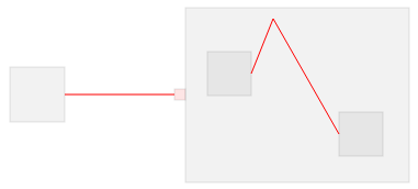
The example below shows how to mix existing positions with automatic layout. To activate this the de.cau.cs.kieler.fixed algorithm can be used, see the properties specification of the n2 node.
Fixed positions are specified for the two child nodes of the compound node n2 and the edge that connects them. Positions can either be directly set to x and y or specified via the position property. Bendpoints are specified via bendPoints, where the first and the last pair of coordinates determines the attachment positions at the node or port and any further pair represents a bendpoint.
id : "root",
children : [ {
id : "n1",
width : 50,
height : 50
}, {
id : "n2",
width : 100,
height : 50,
properties : {
algorithm : "de.cau.cs.kieler.fixed"
},
ports : [ {
id : "n2_p1",
width : 10,
height : 10
} ],
children : [ {
id : "n3",
labels : [ {
text : "n3"
} ],
width : 40,
height : 40,
properties : {
position : "20, 40"
}
}, {
id : "n4",
labels : [ {
text : "n4"
} ],
width : 40,
height : 40,
properties : {
position : "140, 95"
}
} ],
edges : [ {
id : "e4",
source : "n3",
target : "n4",
properties : {
// first and last are src and target
bendPoints : "60, 60, 80, 10, 140, 115"
}
} ]
} ],
edges : [ {
id : "e1",
labels : [ {
text : "e1"
} ],
source : "n1",
target : "n2",
targetPort : "n2_p1"
} ]
};
